
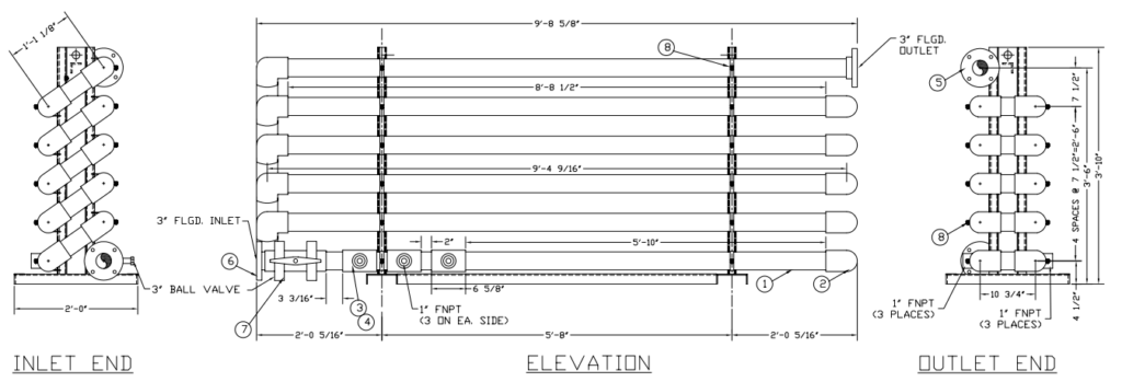
Tube Flocculator
Precise Mixing to form strong, settle-able flocs.
Tube flocculators provide a controlled, energy-efficient environment where coagulants and flocculants can interact with suspended particles, enhancing aggregation before clarification. Their compact design and optimized flow dynamics make them ideal for improving particle removal efficiency in both municipal and industrial applications.
Configure Your Flocculator
Part #
TFL-[FLOW]-[STGS]-[MAT]-[MNT]-[CI]
1
Design Flow Rate
▶
Select the design flow rate for the tube flocculator module. The tube module is sized for the required G-value (velocity gradient) and hydraulic retention time to achieve target floc formation. Standard range is 25–300 GPM.
F025
0–25 GPM
Low-flow; compact single module; small DAF or pilot applications
F050
26–50 GPM
Single module; standard small-medium installation
F100
51–100 GPM
Single or dual module; medium industrial flow
F150
101–150 GPM
Dual module standard; upstream of medium DAF
F200
151–200 GPM
Multi-module arrangement; large industrial or light municipal flow
F300
201–300 GPM
Full multi-module array; upstream of large DAF or lamella clarifier
FCUST
Custom Flow Rate
Flow outside 25–300 GPM range; provide GPM for engineering sizing review
2
Number of Stages
▶
Select the number of tube flocculation stages in series. Each stage provides progressive floc growth at decreasing G-values. Multi-stage arrangements produce stronger, denser floc and improve DAF or clarifier performance.
S1
Single Stage
One tube module; adequate for well-conditioned influent or where space is limited; HRT 2–5 min
S2 Standard
Two Stage
Two modules in series; progressive G-value reduction; stronger floc; HRT 5–10 min; most common
S3
Three Stage
Maximum floc development; challenging wastewater, variable chemistry, or high-solids applications; HRT 10–15 min
3
Material of Construction
▶
Select the tube module and housing material. PVC is the standard for most applications. 304SS is specified for elevated temperature, food contact, or corrosive service.
PVC Standard
Schedule 80 PVC
Chemical resistant; lightweight; standard for water and wastewater service; max ~140°F
304SS
304 Stainless Steel
Elevated temperature, food-grade, or aggressive chemical service; cleanable to hygienic standards
4
Mounting / Installation Type
▶
Select how the tube flocculator module is installed in the process piping. Inline pipe mount is the most compact option. Skid-mounted assemblies arrive shop-assembled with inlet and outlet flanges ready for connection.
MNT-PIPE Standard
Inline Pipe Mount
Module installed directly in process piping; flanged connections; minimal footprint
MNT-SKID
Skid-Mounted Assembly
Shop-assembled on structural skid with interconnecting piping, valves, and flanged terminations; ready to pipe in field
MNT-WALL
Wall / Structure Mounted
Module supported on wall brackets or structural steel; used where floor space is unavailable
5
Chemical Injection
▶
Select the chemical injection arrangement upstream of the tube flocculator. The injection point placement affects mixing intensity and floc quality. Chemical dosing equipment is selected separately under the Chemical Dosing Skid configurator.
CI-NONE
No Integral Injection Point
Chemical injection by others upstream; TFL module only
CI-1PT Standard
Single Injection Point
One flanged or threaded injection quill on inlet header; coagulant or polymer injection
CI-2PT
Dual Injection Points
Two injection points; separate coagulant and polymer injection at optimized locations along tube
CI-PH
Injection + pH Probe Port
Injection quill(s) plus flanged pH probe tee for real-time flocculation pH monitoring
6
Accessories & Add-Ons (Optional)
▶
Select optional accessories. Multiple selections allowed.
Instrumentation
pH-TX
pH Probe + Transmitter
Submersible pH electrode with 4–20 mA transmitter on module body
FT-IN
Inlet Flow Meter
Inline mag meter for chemical flow-pacing and process monitoring
PG
Pressure Gauges
Inlet and outlet pressure gauges; differential pressure monitoring for fouling indication
SAMPLE
Sample Ports
Inlet and outlet sample tees with ball valves for manual jar testing and process monitoring
Piping & Valves
ISO-V
Isolation Valves
Inlet and outlet isolation ball or butterfly valves for maintenance and inspection
BY-PASS
Bypass Assembly
Manual bypass around tube module for maintenance without process interruption
DRAIN
Drain Valves
Low-point drain valves on each module for complete draining and cleanout
FLEX
Flexible Connectors
Expansion joints at inlet/outlet for vibration isolation and thermal movement
Services
Install
Installation Services
Tenco Hydro field installation and commissioning
Configuration Summary
Flow Rate—
Stages—
Material—
Mounting—
Chemical Injection—
AccessoriesNone
0 of 5 configured
Part Number Format
TFLSeries prefix
[FLOW]Design flow range
[STGS]Number of stages
[MAT]Material — PVC or 304SS
[MNT]Mounting type
[CI]Chemical injection config
+[ACC]Accessories (optional)
Ready to Quote?
Send your completed part number to Tenco Hydro. Budgetary pricing within 2–3 business days.
Request a Quote
Engineers Respond Within 2 Business Hours
Complete the configurator above to auto-fill your part number, then describe your application below.
📞
Phone
📍
Location
720 N Heartland Dr Unit K
Sugar Grove, IL 60554
Sugar Grove, IL 60554
🕐
Hours
Mon–Fri, 7:00 AM – 5:00 PM CT
🏭
Specialties
304/316SS welding · ASME stamping
PE stamps all 50 states · In-house fabrication
PE stamps all 50 states · In-house fabrication
✅
Request Received!
A Tenco Hydro engineer will follow up within 2 business hours.
Questions? Call 708-387-0700.